

Application Note · E-mobility & Battery Interfaces
Application Note · E-mobility & Battery Interfaces
Lithium battery projects do not fail because a connector is considered too late; they fail when the connector and cable assembly are treated as an isolated component rather than as part of the installed charge-discharge path. For electric motorcycles, light electric vehicles, industrial battery equipment and related e-mobility projects, the interface may need to bring power, control or monitoring circuits together while withstanding handling, vibration, cable movement and environmental exposure.
This guide is for OEMs, engineering teams and sourcing teams defining an M23 self-locking waterproof connector cable assembly for a lithium battery charging and discharging project. It explains what to confirm before choosing a configuration, what should appear in an RFQ, and where a connector specification must be checked against the complete installed system.
Why an M23 Self-Locking Interface Is a System Decision
In a battery project, the connector does more than create an electrical path. It also shapes service access, mating repeatability, cable routing, strain relief, interface protection and the way an installer distinguishes power connections from control or signal connections. Those decisions affect the battery pack, charger, vehicle or equipment enclosure, not just the connector at the end of a cable.
For this reason, a charge-discharge interface should begin with the project architecture. Define whether the connection is used at the battery pack, charger, controller, service port or another interface. Confirm whether the same mated interface carries power and auxiliary circuits, whether the connection is handled by technicians or end users, and how the cable is supported once the assembly is installed.
Verified M23 Square Self-Locking Configurations
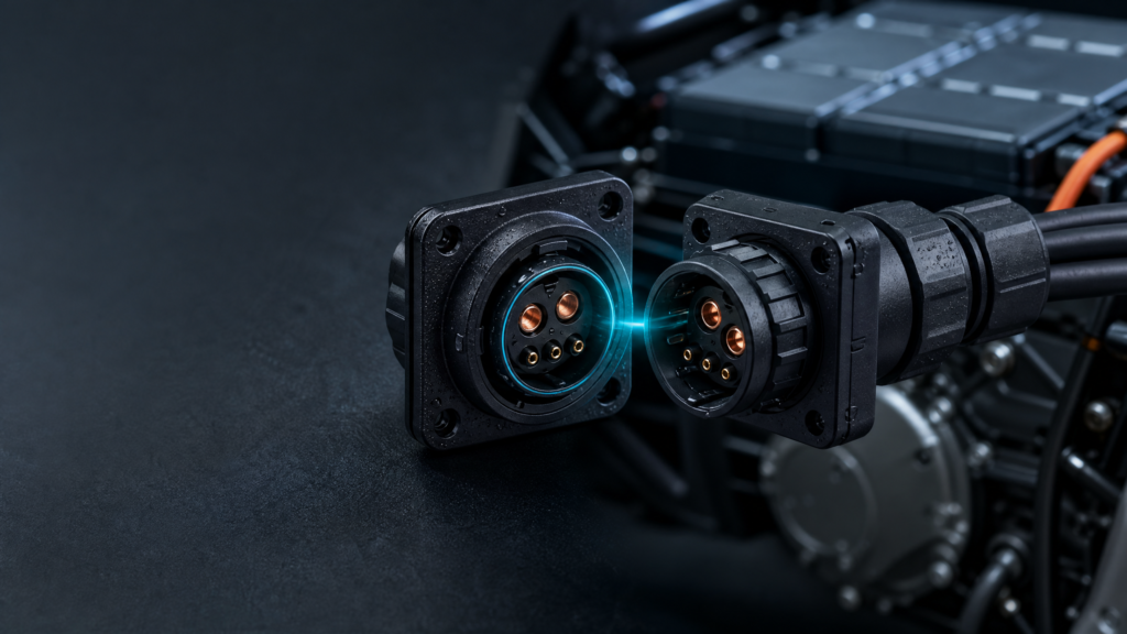
The CONNIXTECH 2025 waterproof connector catalogue includes two verified M23 Square Self-locking configurations. They are available as configuration references for E-mobility and industrial projects; final matching, pin definition and project suitability should be confirmed during engineering review.
| Catalogue configuration | Shell size | Contacts | Rated current | Rated voltage | Protection class | Application tag |
|---|---|---|---|---|---|---|
| M23 Square Self-locking · 2+4PIN | M23 | 2+4PIN | 50A | 300V | IP67 | E-mobility / Industrial |
| M23 Square Self-locking · 5PIN | M23 | 5PIN | 50A | 300V | IP67 | E-mobility / Industrial |
These entries originate from page 9 of the 2025 catalogue. A pin count or rating in a catalogue configuration is not a substitute for a project wiring drawing. It does not establish that every M23 interface, every cable option or every battery system has the same electrical, environmental or regulatory suitability.
Define Power and Signal Before Selecting a Pin Arrangement
Projects involving lithium battery charging and discharging often include more than one circuit function. The RFQ should identify whether the interface is intended for a power path only, whether it also requires auxiliary or control circuits, and which functions must remain electrically and mechanically separated. A 2+4 contact arrangement may suit a project that needs a defined mix of circuit functions, but the actual pinout, polarity, contact assignment and mating logic must come from the system drawing.
| Design question | Why it matters | Useful RFQ input |
|---|---|---|
| Connection location | Battery-pack, charger, controller and service-port interfaces can have different packaging and maintenance requirements. | Interface location, enclosure drawing and access direction. |
| Circuit function | Power and auxiliary circuits may require separate electrical definitions and validation. | System voltage, current, contact assignment and wiring diagram. |
| Mating method | The user, service technician or production operator may have different installation conditions. | Expected mating process, locking preference and service procedure. |
| Cable transition | The cable entry and support path affect the installed assembly. | Cable OD, conductor construction, finished length and strain-relief expectation. |
| Mechanical integration | Panel position and cable direction shape how the interface behaves after installation. | Panel cut-out, mounting method, available space and cable exit direction. |
A complete request tells the connector-and-harness manufacturer how the electrical system, mechanical layout and installation sequence are intended to work together.
Design the Cable Assembly Around the Charge-Discharge Path
An M23 connector is one part of a cable assembly. The finished harness must be planned around the route between the battery interface and the mating equipment. This includes cable length, branching, bend path, fixing points, end terminations, identification and packaging. A short laboratory connection and a field-installed cable can impose very different requirements.
For e-mobility projects, it is useful to define whether the harness runs inside a protected enclosure, along a vehicle frame, through a charger cabinet or to an exposed service location. Ask where mechanical load is taken off the termination, how the cable is routed during maintenance and whether cable movement can place stress on the mated interface. For projects using a molded or assembled cable end, provide the cable diameter and the permitted installation envelope early in the discussion.
The most efficient RFQs include a simple drawing. Even an early drawing that marks the connector orientation, power and auxiliary circuits, cable lengths and open-end terminations can reduce later interpretation. Where a project needs a custom length, labeling, branching arrangement, connector structure or packaging sequence, those details should be reviewed as part of the cable-assembly scope rather than added after the connector has been selected.
IP67 Is Part of the Installed Interface, Not a Standalone Promise
The IP Code is the IEC system used to describe the protection provided by enclosures against access, solid foreign objects and water.1 For a charge-discharge connection, the final environmental outcome depends on the complete installed interface: the selected configuration, mated condition, sealing components, cable entry, mounting orientation, actual exposure and maintenance practice.
The verified M23 catalogue configurations above are specified as IP67. In a real project, that rating should be discussed together with the system’s expected moisture, dust, washdown, condensation and handling conditions. It should not be interpreted as a blanket claim for every cable, every mating condition or every battery installation. The relevant acceptance criteria and validation plan should be agreed for the actual configuration under evaluation.
RFQ Checklist for M23 Battery Connector Cable Assemblies
| Information to provide | Example of useful detail |
|---|---|
| Application | Electric motorcycle, light electric vehicle, industrial battery equipment, charging interface or service connection. |
| Connection role | Battery pack, charger, controller, power distribution, service port or another interface. |
| Electrical definition | Voltage, current, contact count, pinout, polarity and whether power/auxiliary circuits share one interface. |
| Mechanical definition | Panel position, mounting approach, mating direction, cable exit direction and available installation space. |
| Cable definition | Cable OD, conductor details, jacket expectation, finished length, branches and open-end termination. |
| Environment | Indoor/outdoor use, moisture, dust, cleaning approach, vibration exposure and expected handling. |
| Project controls | Required samples, drawing revision, labeling, packaging, inspection records and target delivery date. |
From Drawing to Production-Ready Cable Assembly
CONNIXTECH can discuss matching, drawings and quotation support for the verified M23 configurations. For a new project, the practical process is to review the application inputs, confirm the selected connector and cable approach, define drawings and sample requirements, then move into controlled assembly and inspection for the approved configuration.
The factory’s published manufacturing capabilities include controlled cable assembly and 100% QC. Waterproof, high-voltage, salt-spray and tensile test support can be discussed when relevant to a project; the test method, sample condition and acceptance criteria should be agreed for the exact configuration instead of assumed from a general product name. This keeps engineering decisions traceable and avoids overstating what an untested combination can do.
Frequently Asked Questions
Is the M23 2+4PIN configuration a universal lithium battery charging connector?
No. The 2+4PIN M23 Square Self-locking entry is a verified 50A / 300V / IP67 catalogue configuration for E-mobility and industrial applications. Project compatibility depends on the actual circuit, pinout, mating parts, cable assembly, installed environment and validation requirements.
Can the cable length and cable end be customized?
Project-specific cable length, connector structure, labeling, packaging and cable-assembly details can be reviewed through an OEM/ODM inquiry. Provide a drawing, cable information and the intended connection path so the proposal can be evaluated against the complete assembly.
What should be supplied before requesting a sample or quotation?
At minimum, provide the application, voltage/current, contact definition or pinout, installation location, cable length/OD, interface drawing and environmental expectations. If a final drawing is not ready, an annotated concept drawing is still useful for an initial engineering review.
Define Your M23 Battery Interface with CONNIXTECH
If you are developing an e-mobility or industrial battery project, start with a verified M23 configuration and an RFQ that describes the whole installed interface.